Our AutoCAD Electrical 2010 Training, is a complete self-paced course with over 11 hours of comprehensive lessons, that will teach you how work more productively in Electical 2010. You will learn to create and manage projects, create and edit various electrical drawings, develop reports within the application and output data, and customize the application to your own design requirements. AutoCAD Electrical 2010 is the software for electrical controls designers. Purpose-built to create and modify electrical control systems, Electrical 2010 includes all the functionality of AutoCAD plus a complete set of electrical CAD features. Comprehensive symbol libraries and tools for automating electrical engineering tasks help to save hours of effort, so you can spend more time innovating.
AutoDesk's Electrical 2010 Training Tutorials Covers the Following Topics
Workflow
Course Introduction
Design Environment Similarities
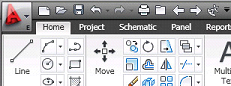
Design Environment Interface
Design Environment Help System
Project
Project Manager Functionality
Project Manager New Projects
Organize Project Lists
New Drawing
Project Drawing List Drawing Descriptions
Plotting From Drawing Lists
Moving Through Project Drawings In Order
Opening & Closing Projects
Copying Projects
Managing Projects
Schematic Wiring
What are Wires and Ladders?
Inserting and Trimming Wires
Wires and Ladders
Inserting Ladders
Revising Ladders
Ladder Referencing
Point-to-Point Wiring Tools
Point-to-Point Wiring Multiple Bus
Wire Number Types
Automatic Wire Numbers and Leaders
Editing Wire Numbers
Wire Numbers and Leaders Configuration
Inserting Destination Signal Arrows and Linking
Inserting Source Signal Arrows and Linking
Schematic Components
Icon Menu Interface
Insert Edit Component- Description Options
Insert Edit Component- Catalog Lookup and Other Options
Insert Edit Component- Children and Linking
Inserting Schematic Components from Lists- Creating and Displaying List
Inserting Schematic Components from Lists- Completing the Insertion Process
Inserting Multiple Schematic Components From Lists
Inserting Schematic Components Equipment Lists
Inserting Schematic Components Catalog List
Connectors Lists
Connectors Options
About Terminals
Terminal Block Properties
Terminal Jumpers
Terminal Associations
Circuits
Multiple Phase Circuits
Schematic Editing
Schematic Editing Location Utilities
Schematic Editing Copy & Delete
Copy Catalog and Location Tools
Swapping and Updating Blocks- Swapping Blocks
Swapping and Updating Blocks- Update Block and Library Swap
Swapping and Updating Blocks- Attribute Mapping Files
Using the Auditing Tools
Updating and Retagging Drawings
Schematic Reports- Creation
Schematic Reports- Report Options
Schematic Reports- Changing the Report Format
Report Output Options
Wire From/To & Component Reports
Panel Layouts
Creating Panel Layouts- Comparing
Creating Panel Layouts- Inserting
Creating Panel Layouts- Schematic Lists
Creating Panel Layouts- Multiple Footprints
Creating Panel Layouts- Nameplates
Using the DIN Rail Tool
Using the Terminal Strip Editor- Inserting
Using the Terminal Strip Editor Tools
Spares & Accessories
Tabular Terminal Charts
Using the Terminal Strip Editor- Jumper Charts
Panel Layout Annotation and Reports- Configuration
Panel Layout Annotation and Reports- Annotation
Panel Layout Annotation and Reports- Bill of Material
Settings and Configurations
Creating Wire Types- Creation
Creating Wire Types- Modifying
Creating Wire Types- Overrides
Using Reference Files
Using Environment Files
Drawing Settings Tab
Drawing Properties- Components Tab
Wire Numbers Tab
Drawing Properties- Cross-References Tab
Drawing Properties-Styles Tab
Drawing Format Tab
Drawing Properties-Configuration Block
Project Settings
Project Options
Project Settings Compare
Drawing Templates
Network or Standalone Installation
Custom Components
Schematic Symbol Naming
Schematic Symbol Templates
Symbol Builder Configuration
Symbol Builder Environment
Symbol Builder Attributes
Symbol Builder Wire Connection
Symbol Builder Tools
Icon Menu Wizard Environment
Icon Menu Wizard- Adding Components
Icon Menu Wizard- Add Submenu
Panel Footprints- Defining
Panel Footprints- Creating
Panel Footprints- Database
Panel Footprints- List
Custom Data
Managing Part Catalog Databases-
Catalog Number
Catalog Subassembly
Catalog Items
Editing the Pin List Database- Pin List
Editing the Pin List Database- New Pin List
Editing the Terminal Block Properties Database- Terminal Block
Updating Title Block Attributes Options
Updating Title Block Internal Attribute
Updating Title Block Attributes- External File
Updating Title Block Attributes- The Process
Automation Tools
Updating Schematics from Spreadsheets
Creating Report Format Files
Generating Automatic Reports
Vault Integration
Working with Autodesk Vault- Logging in, Checking in
Working with Autodesk Vault- Checking out
PLC Modules
Using PLC I/O Modules- Standalone
Using PLC I/O Modules- Fixed Modules
Using PLC I/O Modules- Parametric
Using the PLC Database File Editor- Specifications
Using the PLC Database File Editor- Terminals & Settings
Using the PLC Database File Editor- Attribute Data
PLC I/O Address-Based Tagging
Using the Spreadsheet to PLC I/O Utility- Setup
Using the Spreadsheet to PLC I/O Utility- Layout
Miscellaneous Advanced Tools
Adding Wire Data to Footprints- Wire Connection
Adding Wire Data to Footprints- Wire Annotation
About Cable Marker Symbols
Inserting Wire Fan In/Out Source Signals
Adding Cable Markers
Inserting Wire Fan In/Out Destination Signals and Cable Report
Using the Circuit Builder- Overview
Using the Circuit Builder- Insertion
Using the Circuit Builder- Configuration
Using the Circuit Builder- Recalculating Wire Size
Using the Circuit Builder- Templates
Using the Circuit Builder- Circuit Builder Spreadsheet
Using the Circuit Builder- Inserting Custom Circuit & Options
Using the Electrical Standards Database Editor
Working with Peer-to-Peer Style Drawings
Linking Schematic to Peer Components with Same TAG Values
Linking Schematic to Peer Components with Different TAG Values
One-Line Components, No Wire Number Wires, and Linking to Schematic Components
One-Line Diagrams and the Circuit Builder |